Another test setup: an RC and Auto RIG , where remote control can be used to switch back and forth between the two movement states.
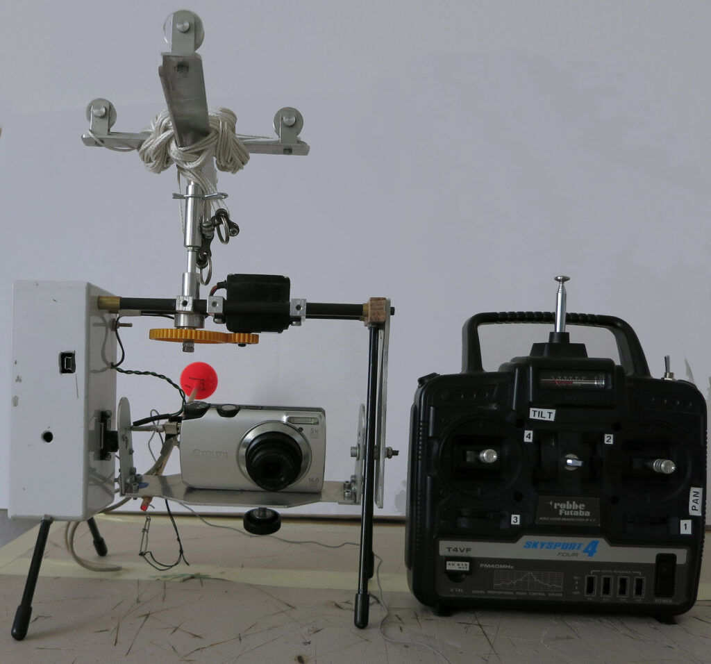
Weight without camera: 572.25 g (+ 16 g for the camera screw)
Description
This rig consists, as the name suggests, of a combination of automatic movement and recording control and remote movement/recording.
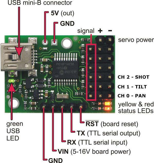
Here too, a Pololu Maestro Micro Servo Controller with 6 channels performs its task for the automatic control function. The programme executed is no different from that of the Auto-Rig presented above. However, the outputs do not go directly to the servos for pan and tilt and to the USB connector of the camera, but to a Pololu 4-channel RC servo multiplexer.
Furthermore, this rig has a receiver part of an (old) 40 Mhz remote control. The cables plugged into this receiver also run to the multiplexer.
The multiplexer is now used to switch between these two independent sources on demand by using a separate channel as input.
Function
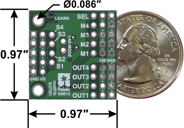
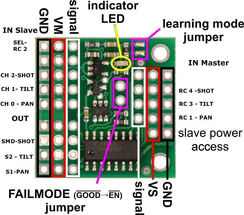
The RC Multiplexer measures the incoming signals on the input labelled SEL, compares them with the presets and decides whether the master (M1-M4) or slave (S1-S4) input signals should be passed to the outputs (OUT1-OUT4). According to the default setting, the passing on to the slave only happens if the pulse length of 1700 μs is exceeded. More details about this component can be found on the Pololu website.
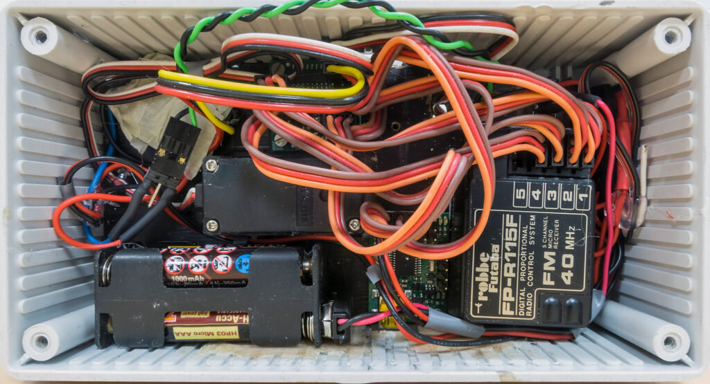
This is what the whole thing looks like. It’s still a bit confusing, so it’s still in the experimental stage. 😉
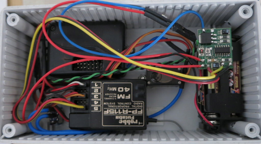
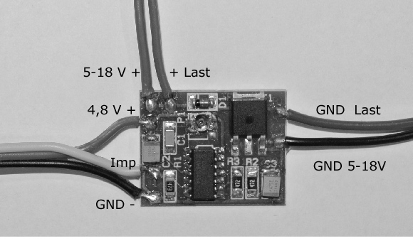
The SMD power switch is used for switching special functions in model making, e.g. headlights, indicators, horn, siren, water pump, etc.
It is connected to a free channel of a receiver or alternatively parallel to a servo. The switching point can be set via a small setting potentiometer.
Here it has the function of switching the voltage I need for the USB connection and ultimately for the CHDK signal with the pulses that can come either from the Maestro-Micro or the RC receiver. It is connected to an output of the RC multiplexer.
Now it’s time for testing and then tidying up inside the control box.
Version 2.0
The boards for the servo control and the switching function are mounted on a wooden plate together with the battery holder and the receiver section, which I can remove completely from the housing. Since the distances between the components are now defined, I have brought some of the cables to the right length. Some of the servo cables are still a bit too long, but I don’t want to shorten them because of the connectors. In short, I have tidied up a bit.
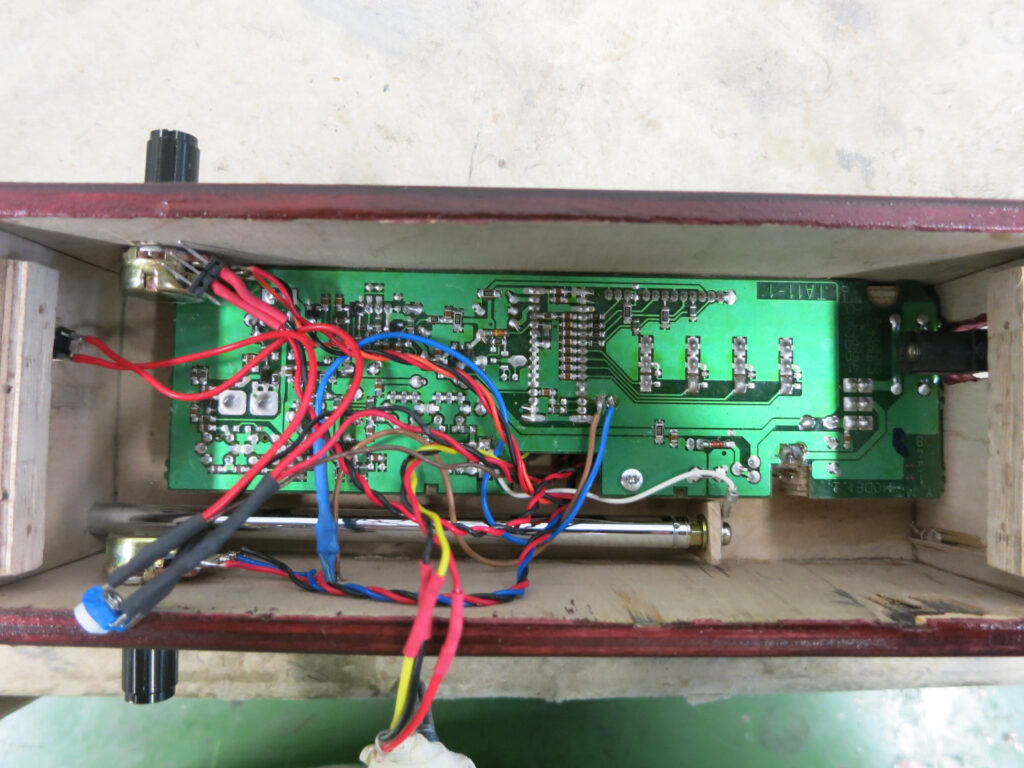
Furthermore, I have worked on the control unit of the remote control. According to pictures from the Kap forum, I packed the circuit boards of the original remote control into a wooden housing. Their circuit boards determine the dimensions of the new housing. The antenna and 8 AA batteries are also housed there. The control sticks have been replaced by a rotary potentiometer with a large adjusting wheel (TILT) and switch (SEL/SHOT) or button (PAN).
More images to follow
.